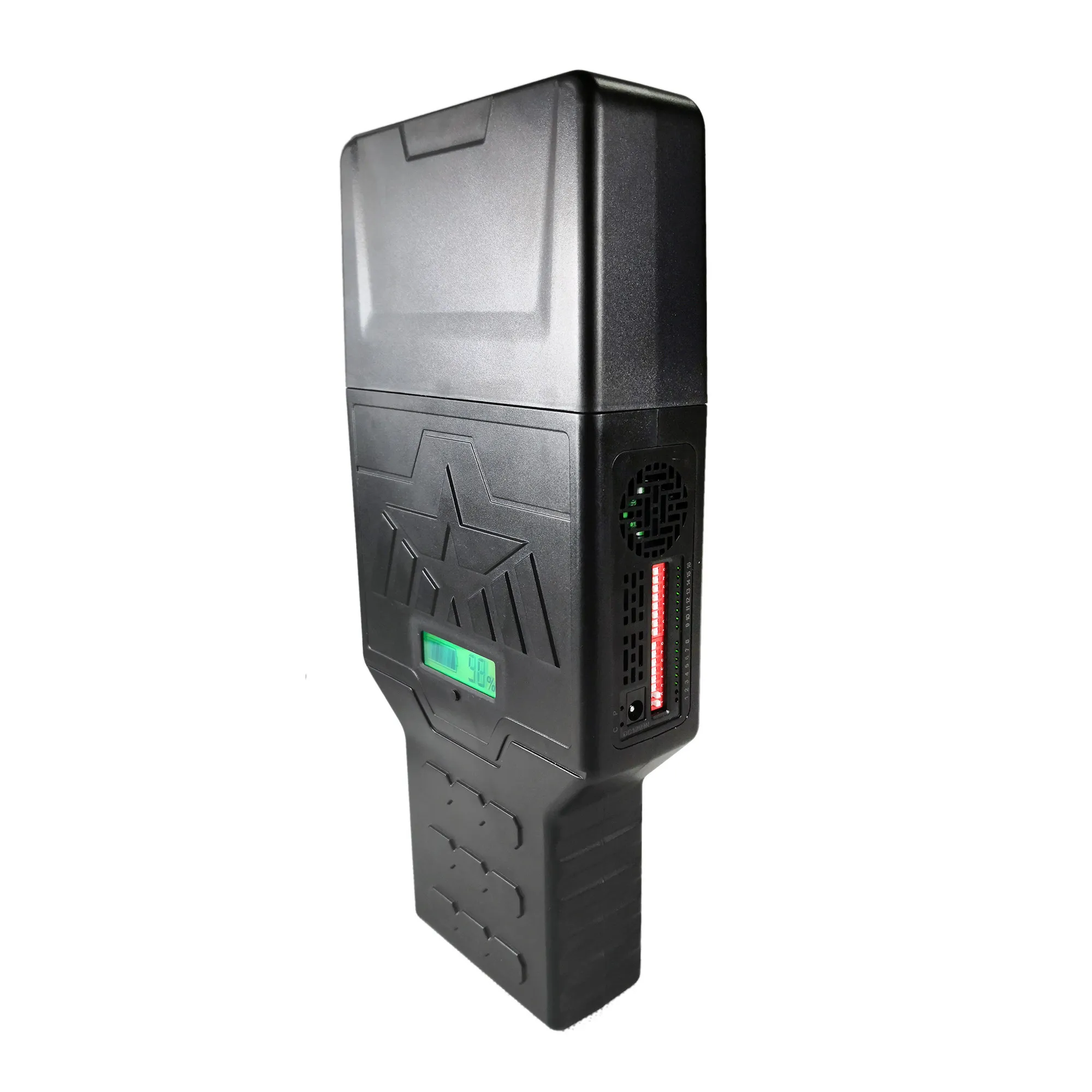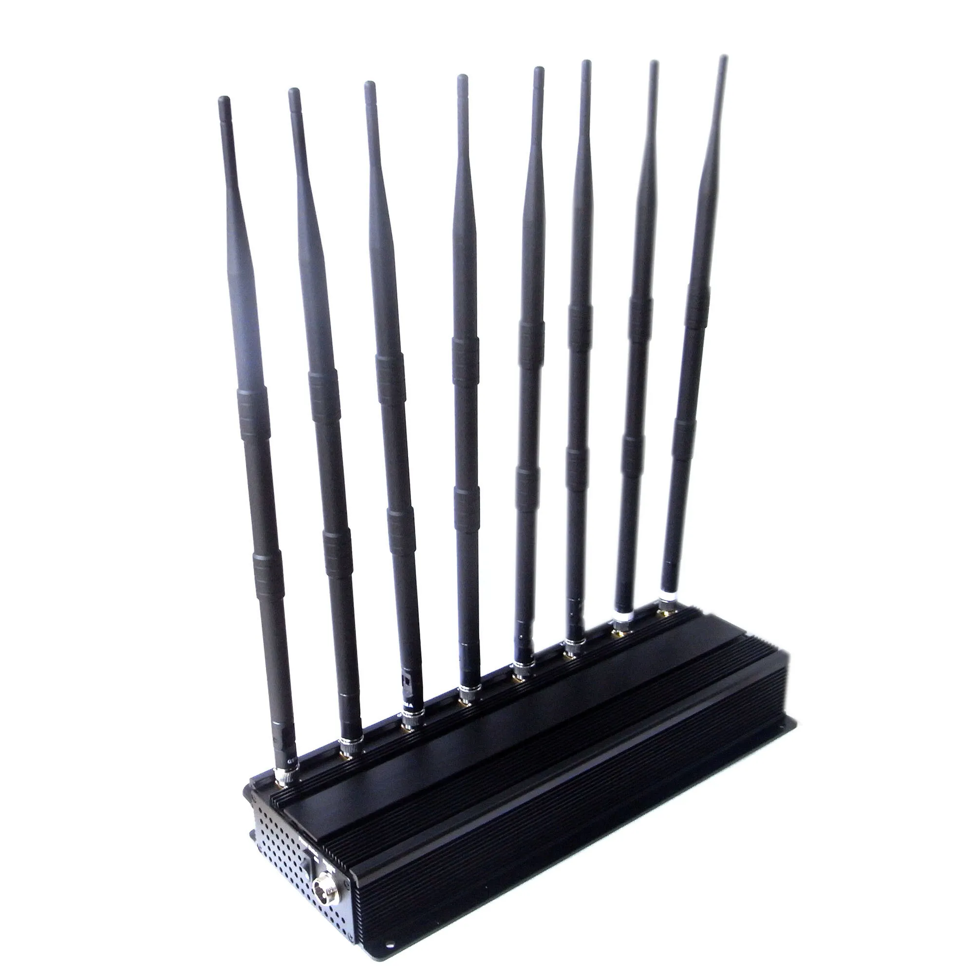
In recent years, with the rapid development of small drones, various safety problems caused by this are also increasing. For example: near the airport, the random flying of small drones threatens aviation safety; the use of small drones to throw drugs and guns into prisons is illegal and criminal. Faced with these increasing security issues, how to counter drones has become a hot topic of research. At present, the technology of countering UAVs is mainly divided into three categories: one is interference blocking, which is mainly achieved through signal interference, acoustic interference and other technologies. The second is direct destruction, including the use of laser weapons and the use of drones to counter drones. The third is monitoring and control, which is mainly achieved by hijacking drone control signals. Because all current small drones need to use radio technology to achieve positioning, remote control, image transmission and other functions. Therefore, the utility model adopts the most practical and cost-effective radio signal interference technology to interfere with the drone, so as to achieve the purpose of causing the drone to lose control or turn back.
The problem to be solved by the utility model is to provide a small drone jammer with wide input voltage range, selectable interference signal frequency band, variable interference signal bandwidth, small size and light weight.
In order to solve the above problems, the technical solution adopted by the present utility model is: a small Drone jammer, including a DC-DC voltage conversion module, an interference signal frequency band selection control module, an interference signal generation unit, an interference signal amplification unit and an antenna;
The advantages of the utility model compared with the prior art are:
1. The DC-DC voltage conversion module has a wide voltage input range;
2. Interference frequency band selection function, you can choose to interfere with the positioning system or communication system of the small UAV, or both systems can interfere at the same time. It is more targeted and flexible, suitable for more occasions, and can also reduce Power consumption;
3. Using voltage-controlled oscillator to generate interference signals, the circuit structure is simple and easy to implement;
4. The small size ceramic antenna design is adopted to make the entire interference device small in size and light in weight.
The functional block diagram of the utility model small UAV jammer, including the DC-DC voltage conversion module, the frequency band selection control module, the interference signal generation unit, the interference signal amplification unit and the antenna. The input end of the DC-DC voltage conversion module is connected with an external Power source, and its output end supplies Power to the interference signal generating unit and the interference signal amplifying unit. The interference signal frequency band selection control module is connected to the input of the interference signal generation unit to control the generation of interference signals in the three frequency bands, and then the generated interference signals of different frequency bands enter the amplification unit of the corresponding frequency band, and finally output to the antenna of the corresponding frequency band.
The block diagram of the new type of interference signal generating unit. The sinusoidal signal generating circuit generates a sinusoidal signal with a frequency of 200KHz, enters three different signal bandwidth adjustment circuits, and then generates 1558MHz~1577MHz, 2400MHz~2483MHz and 5725MHz~5825MHz through three voltage controlled oscillators. Interfering signals in two frequency bands. The signal bandwidth adjustment circuit is composed of three different proportional operational amplifier circuits. The characteristic of the interference signal generation unit of the utility model is that the interference signal is generated by the sine signal through the voltage-controlled oscillator. The circuit structure of the unit is simple, the use of less components is suitable for the miniaturization of the equipment structure; at the same time, the design of the signal bandwidth adjustment circuit is easy debugging.
The input terminal of the DC-DC voltage conversion module is connected to an external Power supply, and then its output terminal outputs a stable voltage for use by the interference signal generating unit and the interference signal amplifying unit. The design of this module enables the utility model to have a wide voltage input range 6.3 V~36V, output 5V, maximum output current can reach 3.5A. The single-chip microcomputer in the interference signal generation unit generates a 200KHz square wave signal, which is then converted into a sinusoidal signal through a low-pass filter, which enters three different signal bandwidth adjustment circuits, and then passes through its corresponding three voltage-controlled oscillators to generate 1558MHz~1577MHz, 2400MHz~ Interference signals in the three frequency bands of 2483MHz and 5725MHz~5825MHz. Among them, the 1.5/2.4/5.8GHZ signal bandwidth adjustment circuit adjusts the interference signals of the three frequency bands to the appropriate bandwidth; the interference signal frequency band selection control signal can be selected by the single-chip microcomputer to select the frequency band of the interference signal, which can be used to locate small drones The overall interference of the system and the communication system can also be single interference, which has high flexibility.


